M Baas
I am a machine learning researcher at Camb.AI. I post about deep learning, electronics, and other things I find interesting.
A 3D printed enclosure for the Prusa i3 MK3S+
by Matthew Baas
A design and implementation of a minimalist 3D printed case for a Prusa i3 MK3S+ 3D printer.
TL;DR: I recently got a Prusa i3 MK3S+ printer, and it is best practice to have an enclosure for a 3D printer to improve print stability and contain noxious fumes given off by certain filaments. Given the dearth of available simple and easy methods, I opted to model and make one myself. I make the 3D models and design process available for anyone to use (see download links later on).
Post overview:
This post will go over the design in following steps:
- Requirements and objectives of the enclosure
- 3D modelling process
- Printing process
- Construction
1. Objectives
Existing solutions for 3D printed cases such as this, this, this, or even this all have the same issue – they require many non-3D printable parts and have a long BOM . My key objective is to make this case using as few non-3D printed components as possible, minimizing the amount of work necessary to go to specialist or large hardware stores which are not too numerous in my location. They also come with many additional features at the cost of simplicity. So my objectives are
Objective: make a minimal enclosure for the Pursa i3 MK3S+ that
- Minimizes the number of unique items on the Bill of Materials.
- Fully encloses the printer in its default setup (no moving printing spool location or other more complicated changes to default printer setup) – the printer should just be able to be physically placed inside the case and work.
- Is loosely air-tight: there should be minimal airflow or temperature exchange between the inside and outside of the printer during printing (i.e. when the printer is closed).
- Is made with completely open-source tools (no pricy AutoDesk Corp. products).
To this end, I define the Bill of Materials up front:
Bill of Materials:
- 20x
M3 x 10mmscrews and hex nuts. - 12x
M3 x 16mmsheet metal screws (M3 wood screws or any other M3 screws with a taper will work). 56cm x 56cm x 1cmplywood baseboard to put the printer on (or any other56cm x 56cm x 1cmmaterial that the screws used for 2. are compatible with).~2kgPETG or PLA filament.- [hardest to obtain] A clear
56cm x 56cm x 65cmPVC cube cover. All faces should be solid PVC except one of the 56x56 cm faces, which will slot onto our enclosure stands.
Nice and short. Unfortunately, depending on your location, the last item might be slightly harder to come by, but luckily in my area it is very easy to obtain such clear smooth PVC covers. Alternatives include a large transparent recycling plastic bag, or even a blanket if you don’t mind not seeing the print progress.
2. 3D modelling
For 3D modelling I use two tools – Blender and CAD Sketcher. Blender is a truly wonderful open-source 3D modelling program typically used for animations, sculpting, and other artistic 3D modelling use-cases. That is where CAD Sketcher comes in – it is an open-source (GPL license as well, nice!) plugin for Blender which adds the parametric modelling functionality common to precision CAD packages (AutoCAD, Rhino, etc.).
With Blender + CAD Sketcher, we have a fully functional, stable, open-source, and feature rich precision parametric modelling program to make our model in. It took me a while since blender does have somewhat of a learning curve, but eventually I managed to design a decent set of parts comprising the enclosure.
Parts
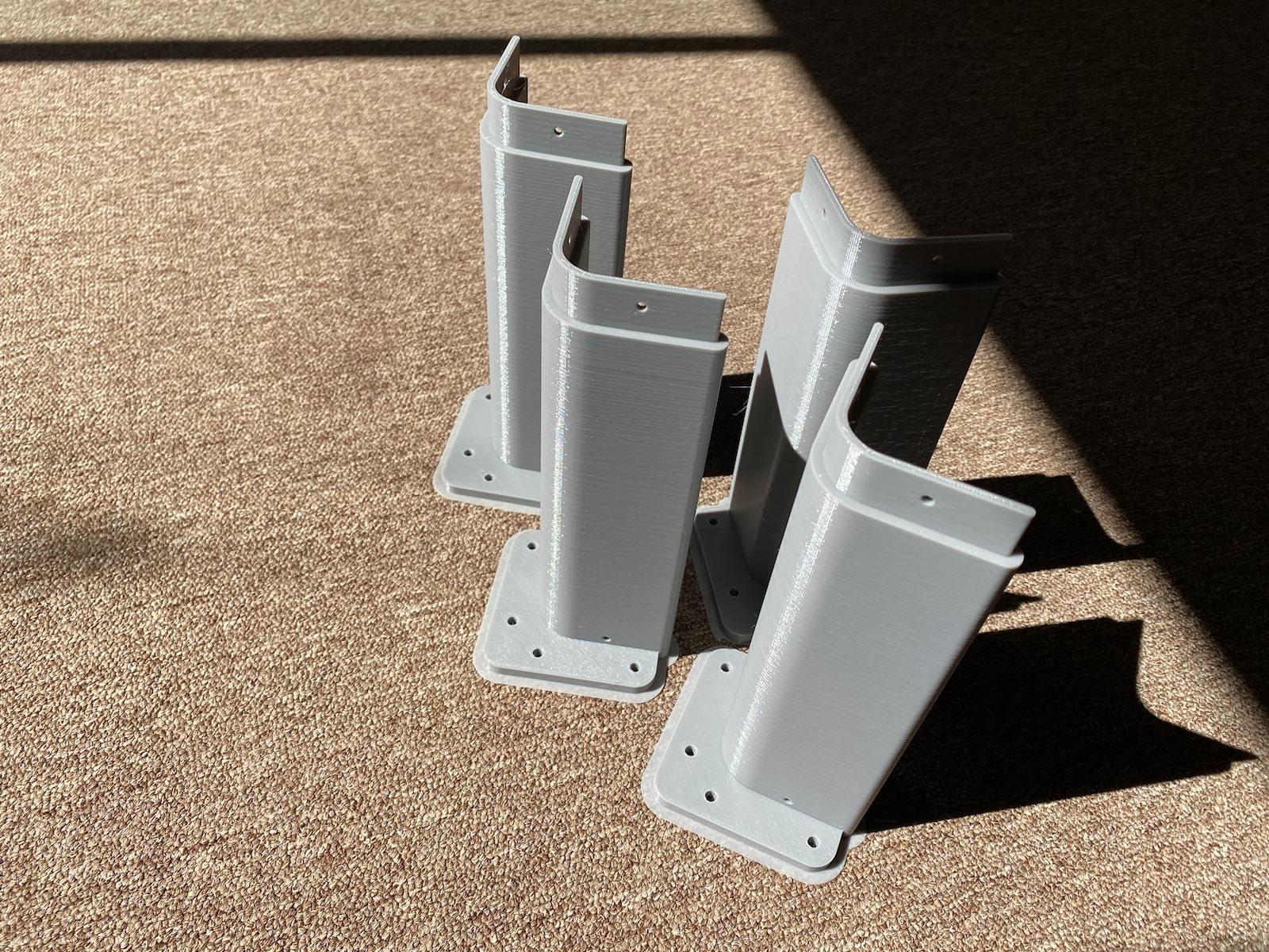
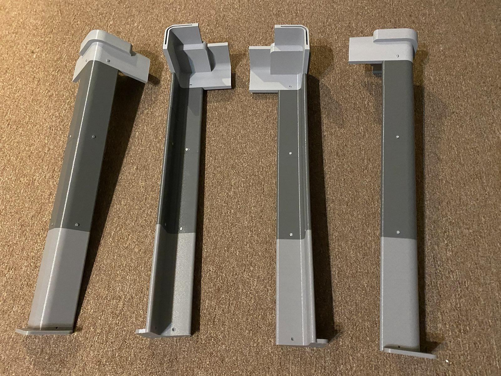
The printer enclosure consists of 4 unique parts – the foot, the the leg, the head, and the arms, shown below.
Figure 1: top-left view of all parts
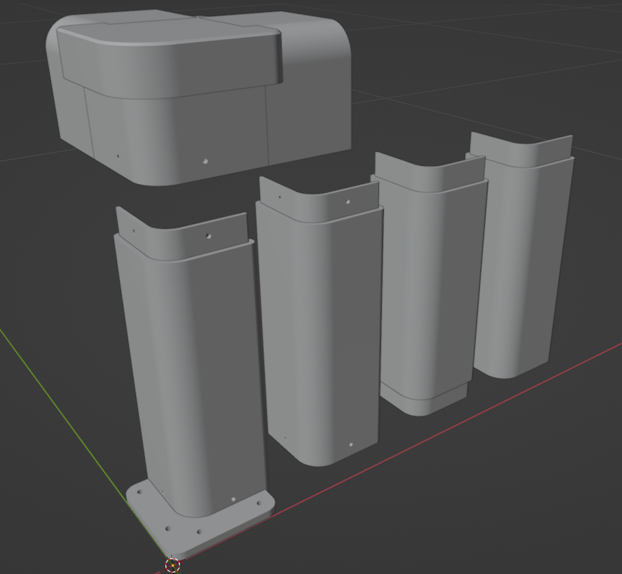
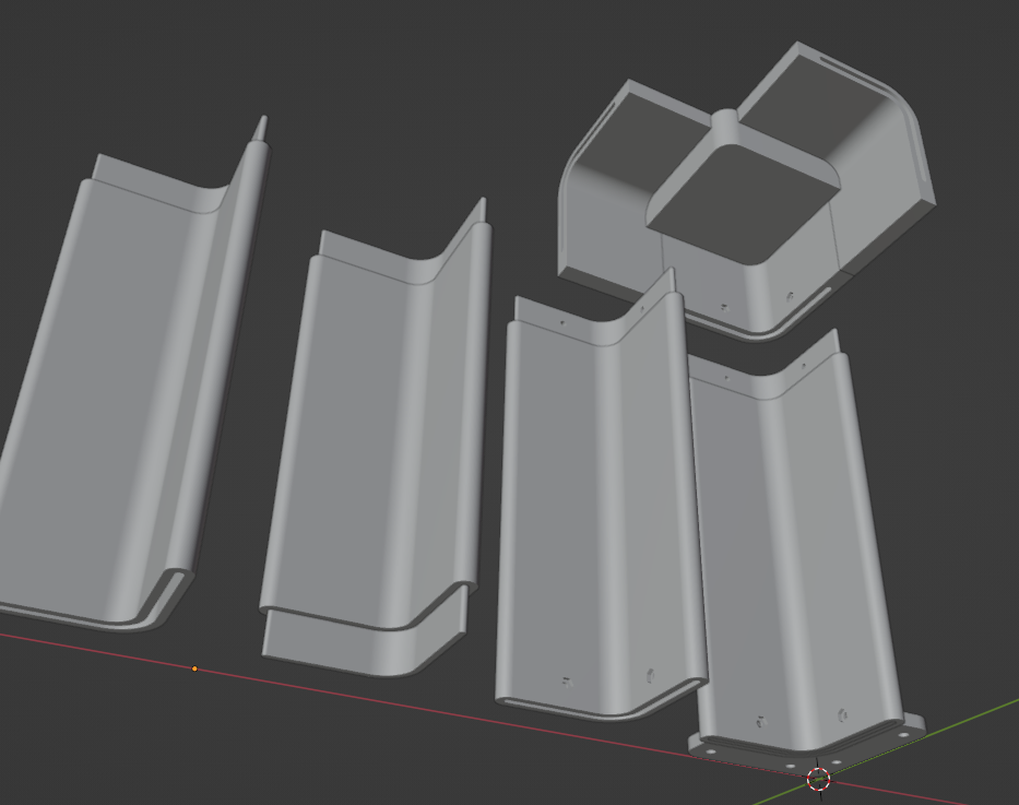
Figure 2: bottom-right view of all parts
Concretely, each of the parts are labelled (front view):
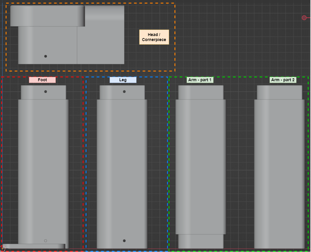
Where:
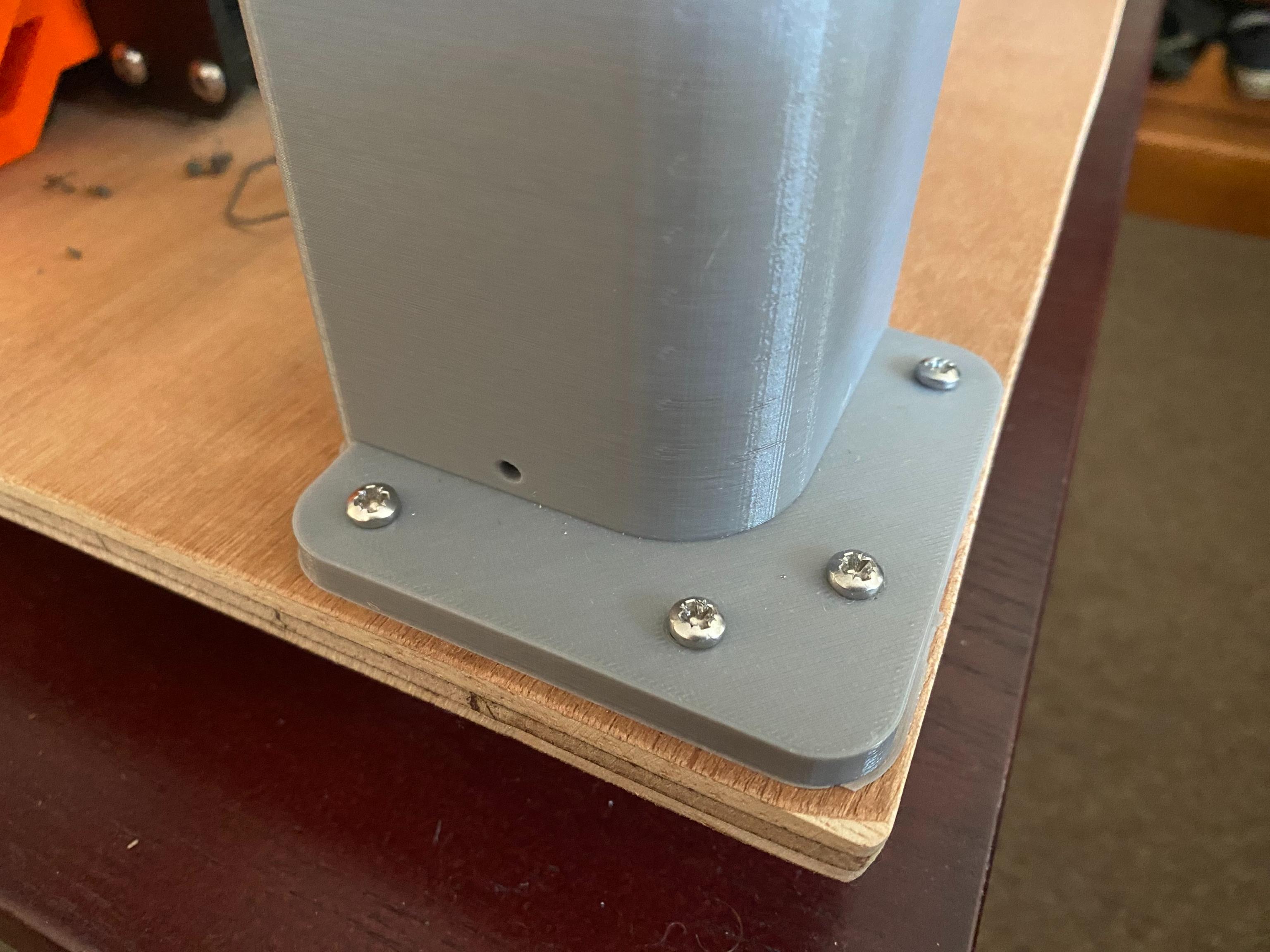
- The foot screws into the wood baseboard using the tapered screws.
- The leg is stacked atop the foot and itself multiple times to make the enclosure the right height we need.
- The head / cornerpiece connects the topmost leg to to the arms and is, well, the corner of the enclosure.
- The arm is split into 2 parts for easier printing and connects one head / cornerpiece to another.
The legs, feet, and heads screw into one another with the M3 x 10mm screws and hex nuts with a nice inset such that the surface of the model (one screwed together) is flush – a technique commonly used in 3D printing to great effect!
Parametric shape definitions
Since we used the CAD Sketcher blender plugin, each of the common components and shapes making up these models are defined as a fully defined parametric set of geometry and constraints. For example, the bottom part of the foot that the tapered screws are used on is defined using the sketch:
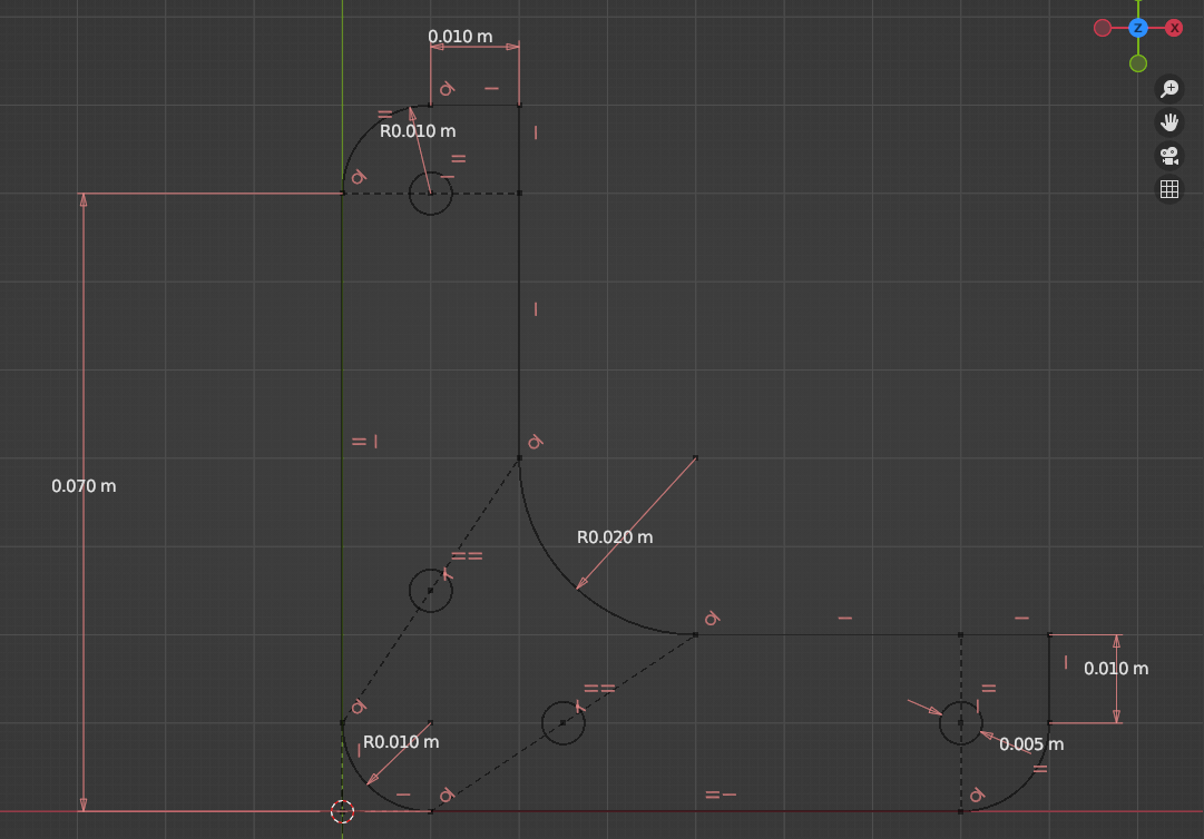
So if you wish for something slightly different in your design, it is fairly easy to just change one of the values here (e.g. changing size of the baseboard holes to fit M4 or M5 screws) will update the 3D model nicely. I’m aware that doing this with extremely heavy and expensive products like AutoCAD also make this a breeze, but being able to do this with purely open-source (even GPL!) products is very cool I think.
3. Printing process
Now with these models, we export them to STL format with blender and load them into your favorite slicer. I use Prusa Slicer since it works really great with their printers, and is fully open source (with an even stronger AGPL v3 license :D). With the sliced models (i.e. gcode files), I simply load them onto the printer and print away!
Concretely, over several days I print the following:
- the foot four times: one for each corner.
- the head four times: one for each corner.
- the leg eight times: two stacked on top of each other for each vertical edge of the enclosure.
- the arms (part 1 and 2) four times: one for connecting each adjacent head.
And that’s it, no post-processing of the printed parts are required so long as the print came out clean. On to construction!
4. Construction
Once all the parts are printed, assembly is straightforward: plug all the plastic parts into each other with the appropriate grooves, then use the M3 x 10mm screws and nuts for all the open screw holes and nut insets.
Then, the full frame is placed on the plywood baseboard and screwed into the wood with the M3 x 16mm tapered screws (drilling guiding holes might be required depending on the kind of screw used for this, I had to drill tiny guiding holes in my case beforehand).
In more detail:
- Here are the four feet printed out (note my slicer used a brim, they can be torn off if desired).
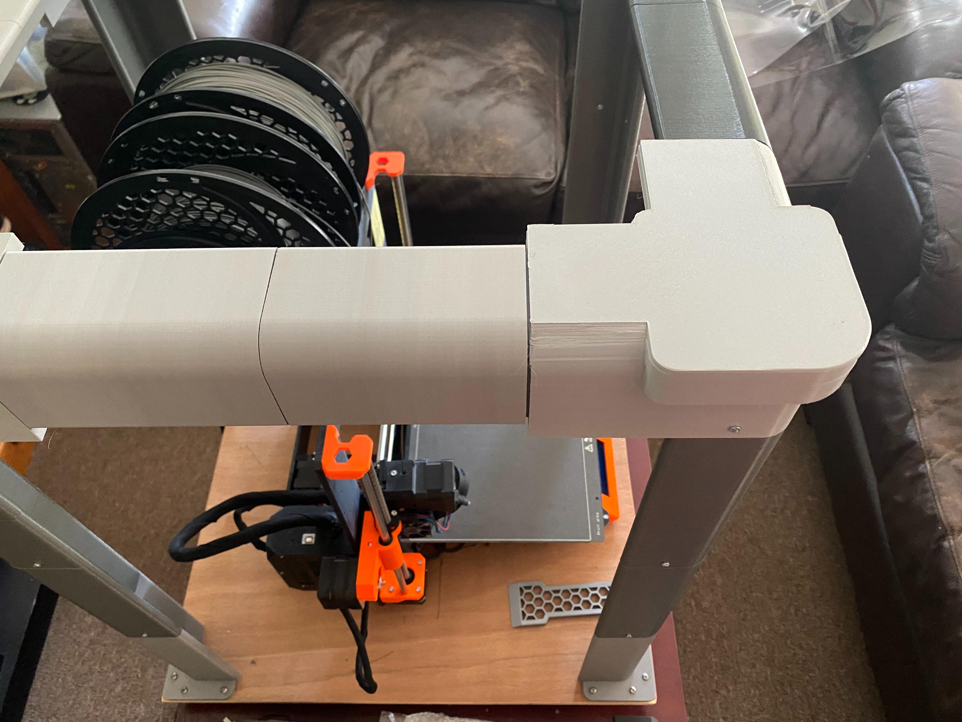
- Once the legs and heads / cornerpieces are done printing, they are slotted into one another where appropriate with the grooves provided. Each connection between two parts is secured with 2
M3 x 10mmscrews and hex nuts. After this, the pieces look like:
- Then, for each pair of Arm part 1 + 2, connect them together and then use the arms to join the cornerpieces together. Since there is minimal vertical weight on the joints of these pieces, they are not secured with screws and simply have a tight fit into one another using the groove provided. The fully constructed frame looks a bit like (coke can provided for size context):
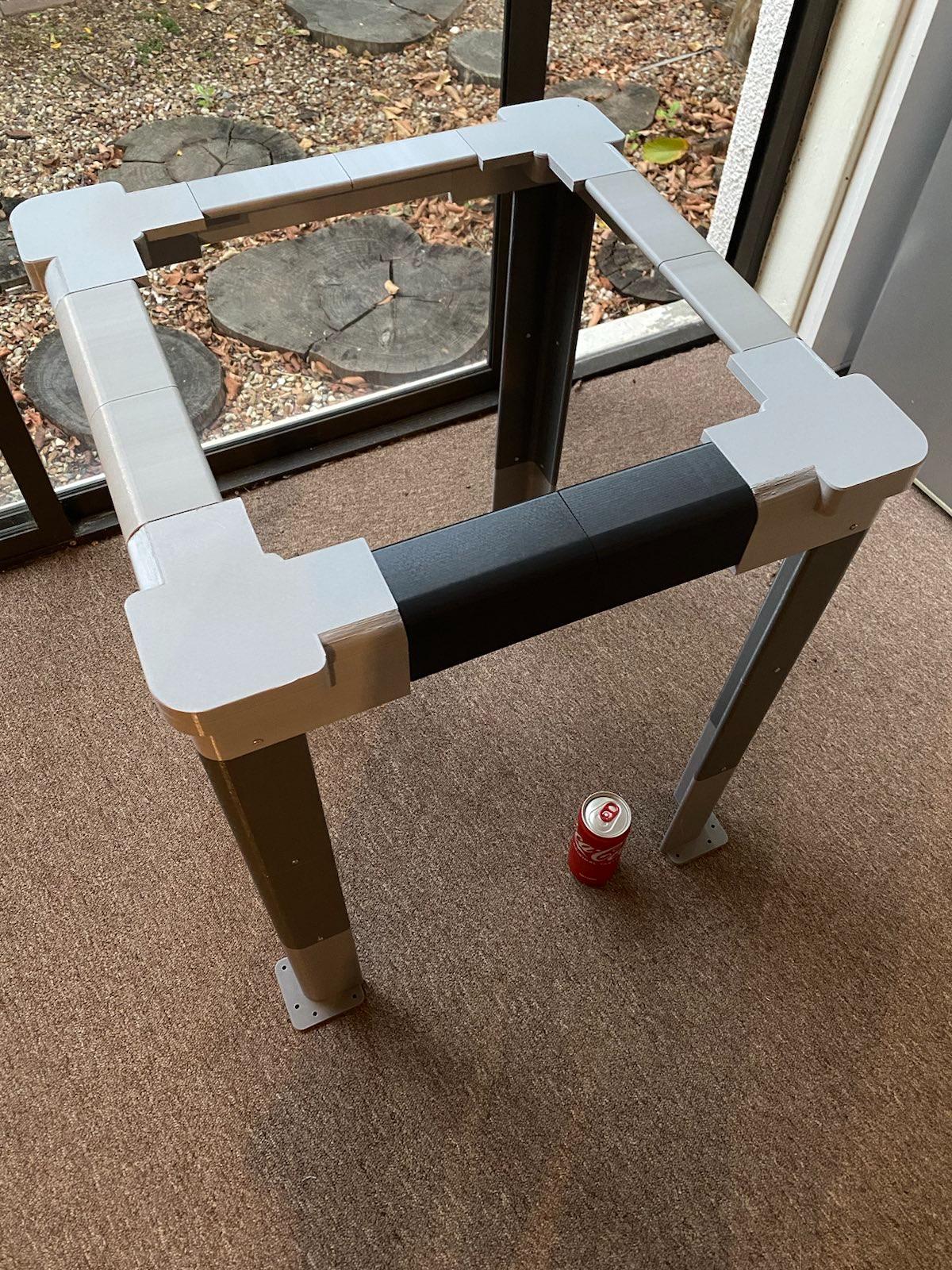
PS: I used black filament for the one arm to mark the front of the frame (that and I ran out of light grey filament).
- Now we lower the completed frame onto the plywood baseboard, and simply screw in the tapered screws into the wood.
In the corners we have screwed on the frame to the wood baseboard with tapered screws. Four is probably overkill, but it is quite study.
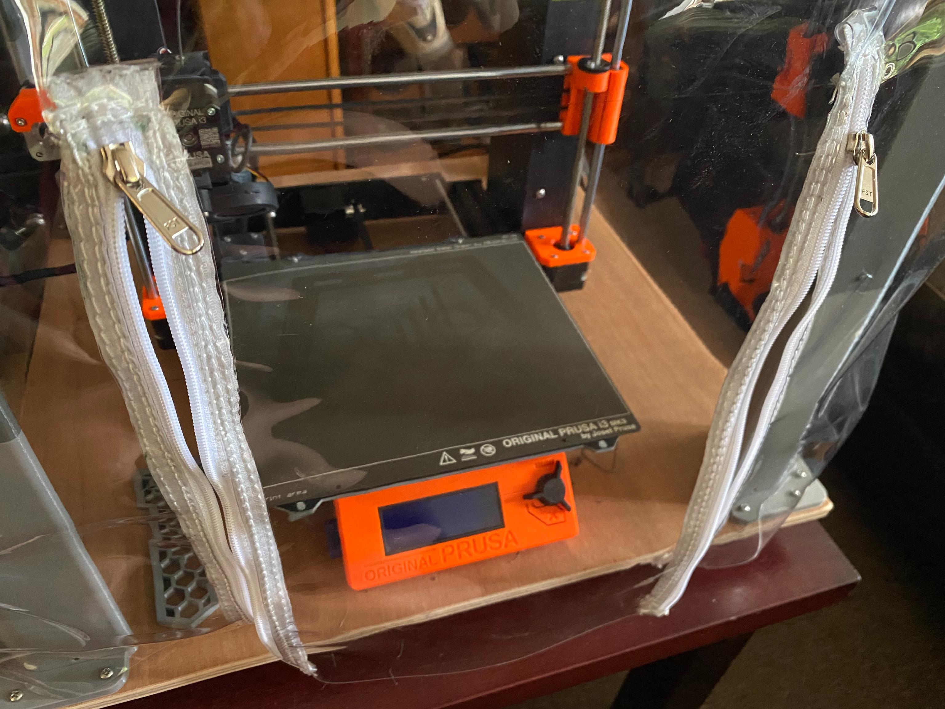
- The final step is to drop down the clear PVC cover. This step is fairly trivial and just involves lowering down the PVC cover onto the completed assembly:
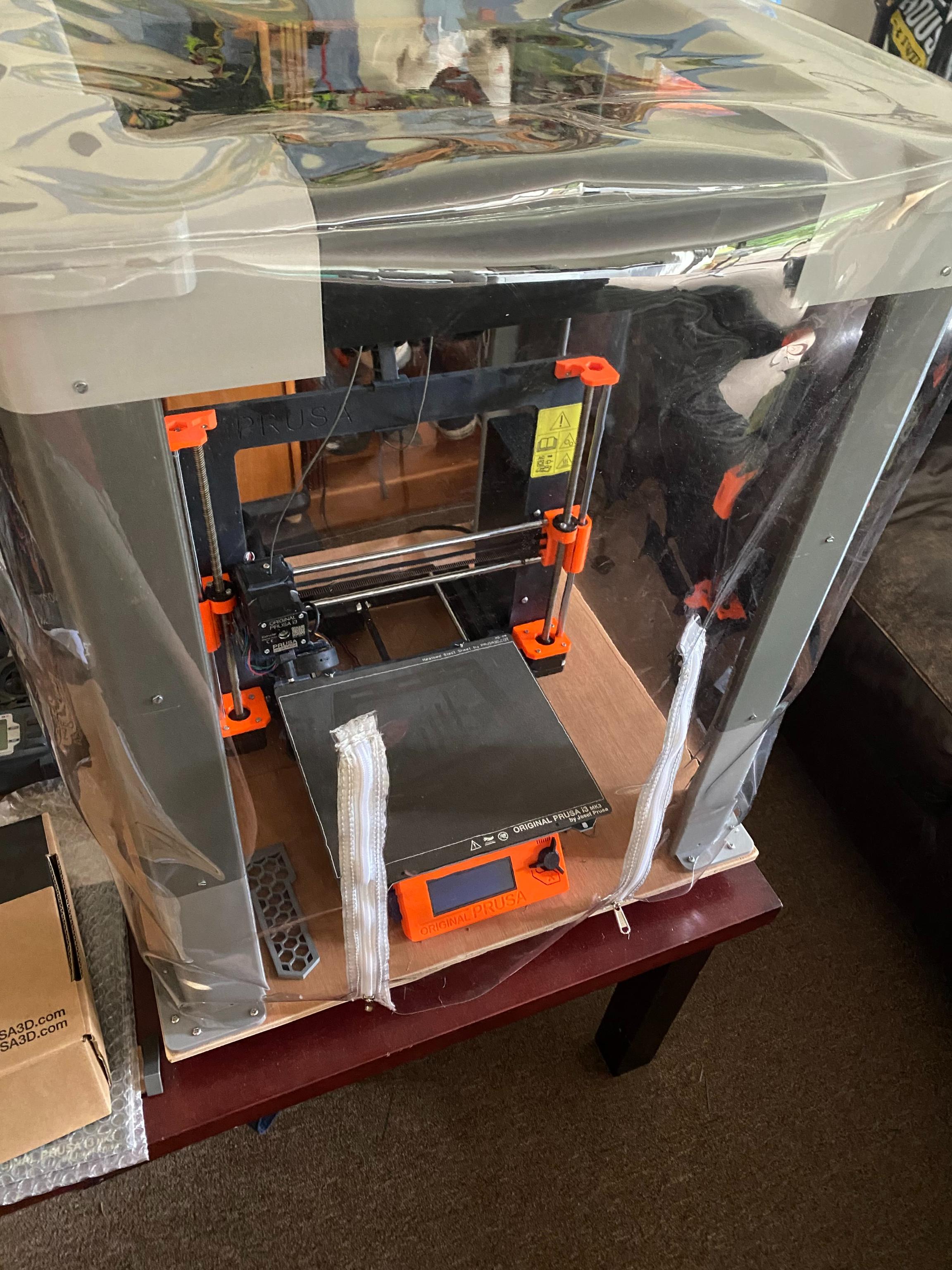
In my cover I also requested two zips on the front to act as a small opening door to access the print results and control panel – it works quite nicely:
And that’s it! Construction complete.
6. Conclusion
Ultimately, the design and construction was a success! While the cover is not perfect (it does not offer a perfect air seal or a vent to exhaust fumes from more hazardous filaments), for a first attempt at such a project I am satisfied with the results because it satisfies our four main objectives from earlier.
If you’d like to use my model or modify it, go ahead! Here is the full blender model file so you can edit it or export to stl..
I hope you enjoyed this little journey into making a minimal 3D printer cover using only open-source tools. As usual, if you have any suggestions or spot a mistake somewhere, please get in contact on the about page.
Thanks for reading :)
tags: 3d printing - prusa - blender - cad sketcher