M Baas
I am a machine learning researcher at Camb.AI. I post about deep learning, electronics, and other things I find interesting.
Building a performant 3D printed microscope in South Africa for under R2000 ($110)
by Matthew Baas
A brief guide on making a performant, largely 3D printed microscope while on a budget, using suppliers available in South Africa.
TL;DR: optical microscopes that can achieve 100x-1000x magnification are very expensive. But, with some 3D printing and specific parts, a nearly-as-good product can be made for under R2000/$110. This post describes how to make such a 3D printed microscope, and some practical considerations for its use.
I will be assuming you have a basic idea of what 3D printing and a microscope is, and just about nothing else :). I myself have minimal experience with microscopy or optics. For those already well experienced in microscopy or microscopes, or already have access to a good one, this might be of less use to you.
1. Microscope basics
A standard optical microscope consists of a few different components, illustrated below:
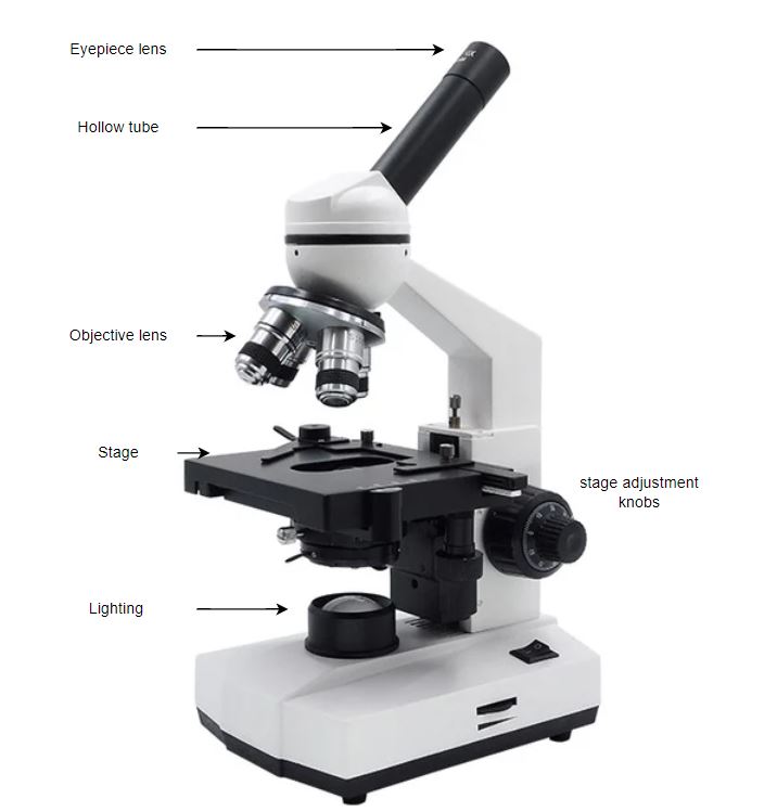
The optics part is made up of 2 lenses – the eyepiece lens (where one puts their eye or phone camera) and the objective lens. Typically the objective lens provides the majority of the magnification, and the eyepiece the secondary magnificatio. Both eyepiece and objective lens are complex objects, often consisting of a many lenses arranged in careful sequence. Multiple objective lenses of different fixed magnifications are attached on a single ‘objective turret’ that can easily be rotated to allow the user to effectively ‘zoom in’ and ‘zoom out’ by changing to higher/lower magnification objective lenses.
Microscopes of the design above can range from (as of December 2024 in South Africa) R5500 to over R200 000. Cheaper ones can be found, but are the expected cheap tat that does not actually provide you the advertised magnification, or has other defects so substantial as to make the microscope useless. The goal here is to substantially reduce this cost, i.e. to make a comparable ~R10 000 microscope for under R2000.
1.1 Microscope design
The design we will go for is a slight modification of the Galileo modular microscope, a good practical design by XVIIarcano. The ‘hard part’ of making the 3D models has already been done by XVIIarcano, and I have only high praise of their work. We will use his design with only slight modifications.
Concretely, the design we’ll use is as follows:
- Optics: a 10x eyepiece lens and 3 objective lenses: a 10x, 40x, and 100x lens, giving a maximum magnification of ~1000x, which is near the limit for optical microscopes.
- Lighting: we will use a ring LED lamp, that, depending on how it is positioned, allows for either bright-field (light shines through specimen into objective lens) or dark-field (light shines on the specimen at an angle so the main light beam does not enter the objective lens, only reflected/scattered light) microscopy.
- Body: the Galileo main body, with the following modifications:
- The alternate rack-and-pinion stage design is used instead of the default galileo stage.
- The objective holder of the default galileo design is replaced with the 3-lens rotating objective turret, allowing for easy change of magnification levels.
- The BYO Illumination module of the base galileo has it’s height (z-axis) scaled by 2x, to make more room for different kinds of lighting designs.
A very nice part about the Galileo design is that eyepiece holder also allows for a 3D printed phone holder, with several variants available for different sizes of eyepiece lenses. This allows one to use their phone to take photos/record the images from the microscope, and they come out very clearly!
1.2 Bill of materials
3D printed items:
- All appropriate parts of the Galileo microscope on printables, as well as the rack-and-pinion stage and rotating objective turret extensions.
- Stage clips (buying these in isolation in South Africa does not appear possible…): I made 3D models for stage clips here, just print 2x of them.
With all the material in total, this should take around 1kg of filament.
Non-3D printed items:
Below I list the items, their prices prices, and an example link to buy each, as of 2024-12-26.
| Category | Item | Cost (ZAR) | Example supplier link |
|---|---|---|---|
| Microscope body | 1m of 12mm diameter hollow aluminum rod | R 100 | link |
| Microscope body | 1kg PETG 3D printing filament | R 300 | link |
| Optics | 10x objective lens | R 205 | link |
| Optics | 40x objective lens | R 267 | link |
| Optics | 100x objective lens | R 269 | link |
| Optics | 10x widefield eyepiece lens | R 315 | link |
| Optics | 5ml immersion oil | R 50 | link |
| Stage | microscope slides and coverslips | R 90 | link, link |
| Stage | lamp (optional) | R 458 | link |
| Miscellaneous | nuts, bolts, nylocs and compression springs | R 150 | |
| Total | R 1746 | ||
| (+ optional lamp) | +R 458 |
In total, just under R2000 if you already have a lamp/light source, and just over it if you don’t. And, given the quality of images you’ll see later in this post, I think you will find the cost-performance combination of this setup quite hard to beat.
2. Construction and practical tips
The construction largely follows the build instructions in the readme’s of the printables instructions, as well as the github readme by the original author.
Some practical tips for assembly in addition to the official build instructions:
- The one thing which I found is optional (especially since it is not super easily procured in SA) is the 4mm outer diameter PTFE tubing. Leaving this out is not a train smash.
- For the ballast, a good pick is some spare heavy nuts/bolts, then use epoxy (e.g. Pratley’s epoxy) to seal it all into the ballast cavity.
- For springs, you’ll either need to go to a spring shop and pick out the right ones, or simply order one of the compression spring kits on takealot (example) – it will have all you need and more.
- The locknuts / nyloc nuts are critical and should not be substituted with regular nuts. They give the stage adjustment knobs the ability to turn nicely.
- Remember to scale the z-height by 2 for the BYO illumination model in your slicer program. This gives you much more room to work with for different kinds of lamps/lighting.
- For the rotary turret petals, you may need to load the STL into your favorite editing program (e.g. OpenSCAD) and just re-apply the RMS threading to the petals. Concretely, I use threadlib for OpenSCAD and here is my code to edit the petal stl file:
echo(version=version());
$fa=1;
$fs=0.2;
use <threadlib/threadlib.scad>

tube_len = 160;
d_out = 24.4;

module objective_holder() {
    difference() {
        cylinder(h=4.9, d=d_out);
        translate([0,0,0.3]) scale([1.016, 1.016, 1]) tap("RMS", turns=6.2);
    }

}

module main() {
    translate([0,0, 0])
    objective_holder();
}

difference() {
    translate([-209.2, -193.6, -81.6]) {
        import("/path/to/petal-x3.stl");
    }
cylinder(h=8, d=24);
}

main();
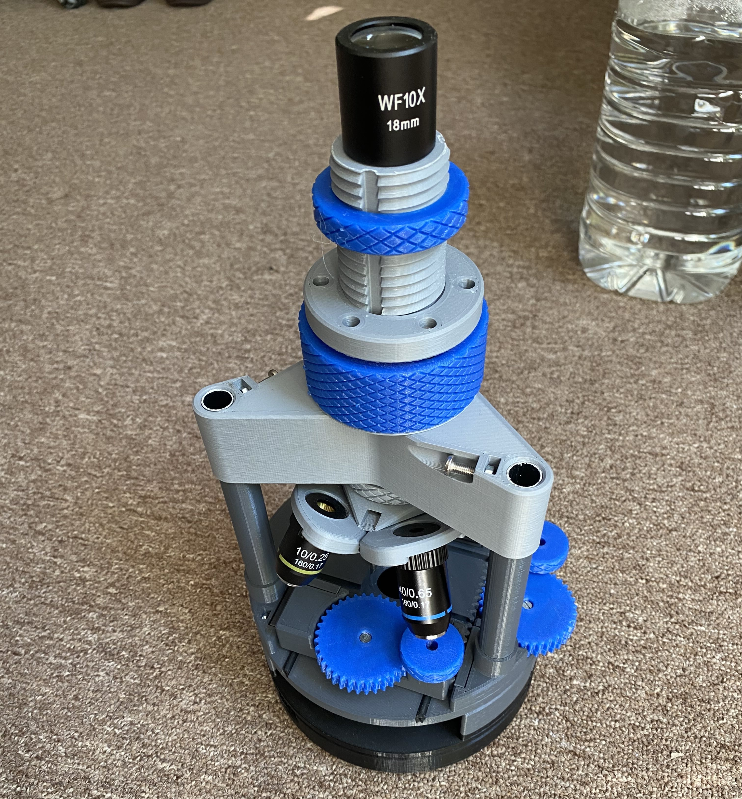
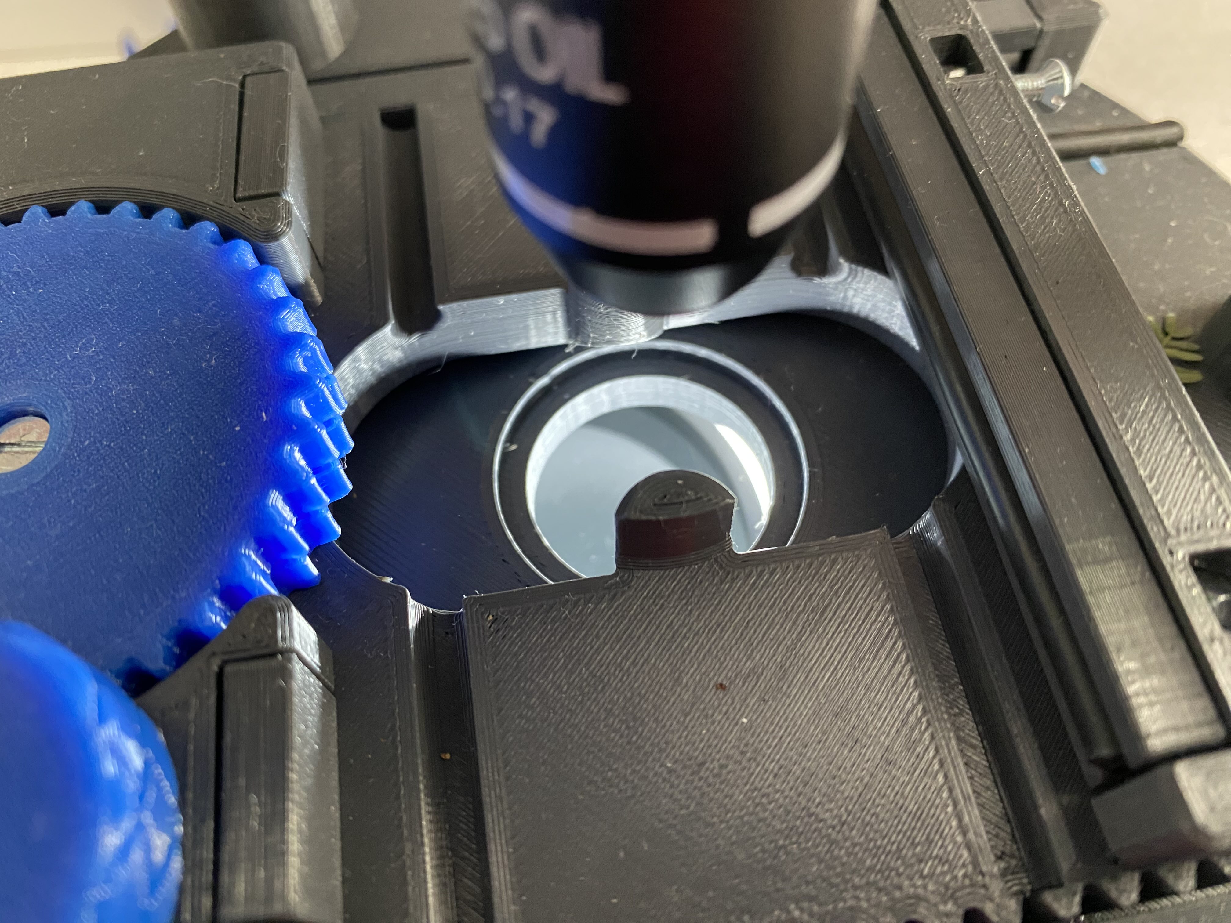
Once constructed, it should look similar to the image below:
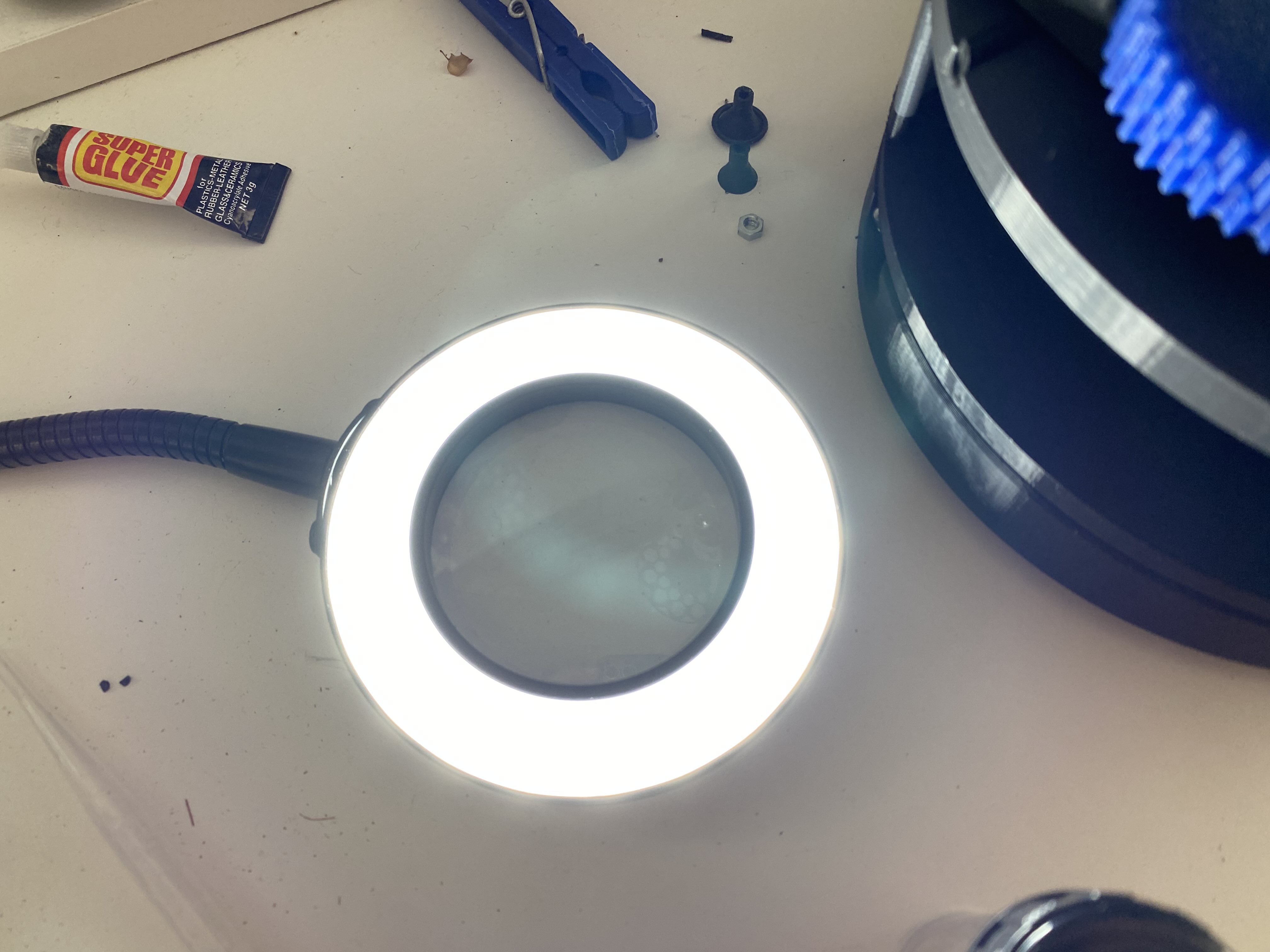
Lighting
The lamp in the parts list above has a circular ring of LEDs with a magnifier in the middle:
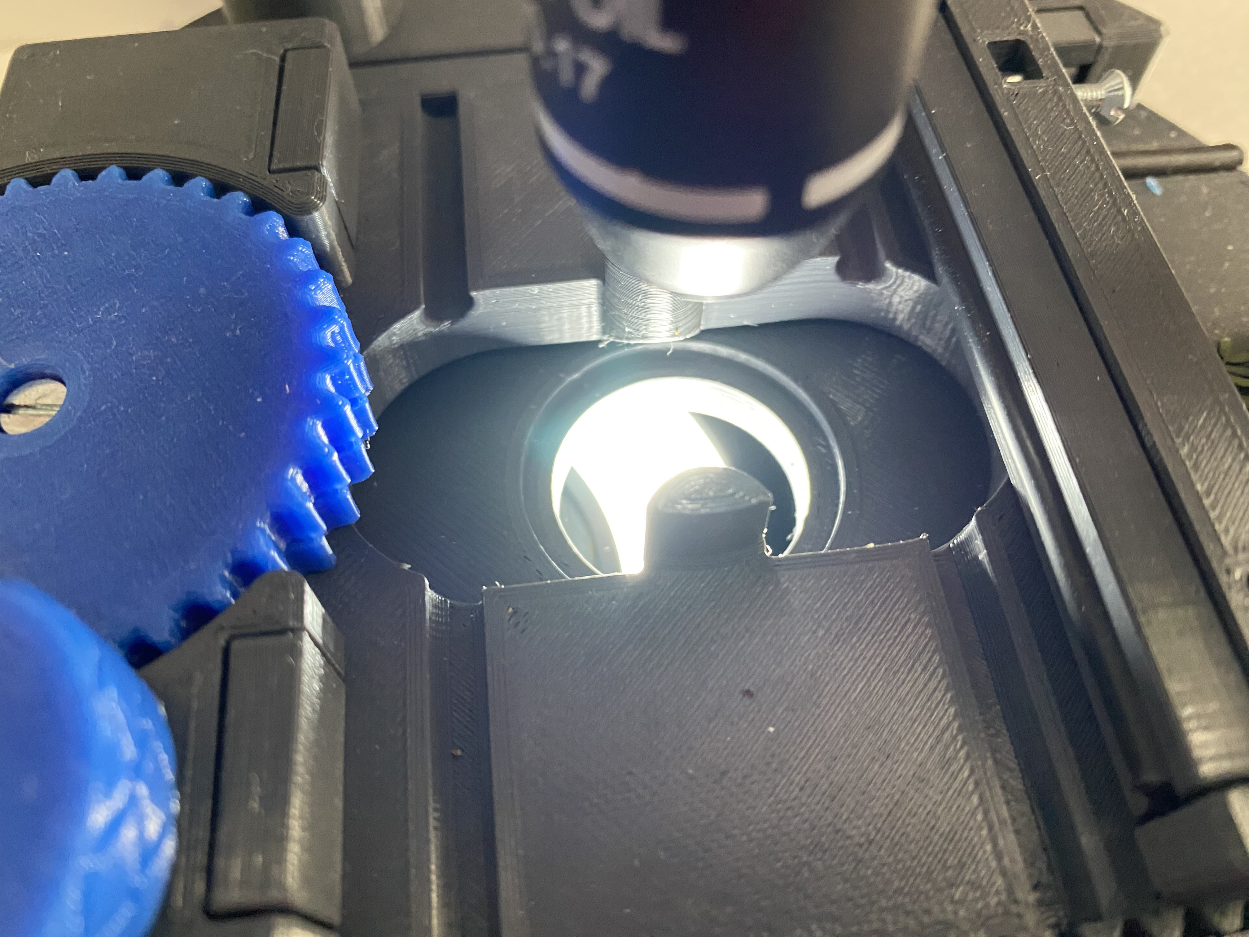
The circular ring of LEDs can now simply slide into the lighting slot, and how it is positioned can determine whether a ‘bright-field’ or ‘dark-field’ effect is given when looking. For example, bright field illumination can be achieved by positioning the band of LEDs directly below the stage:
Alternatively, if the band is placed at an offset so that the light illuminates the specimen but does not shine directly into the objective lens, then a dark-field illumination effect can be obtained:
And that’s it! You now have a microscope :).
3. Optical performance
Using the phone holder, we can now place specimens under the microscope and take photos/videos with a smartphone to capture the results, and profile the performance. So, let’s dive into it:
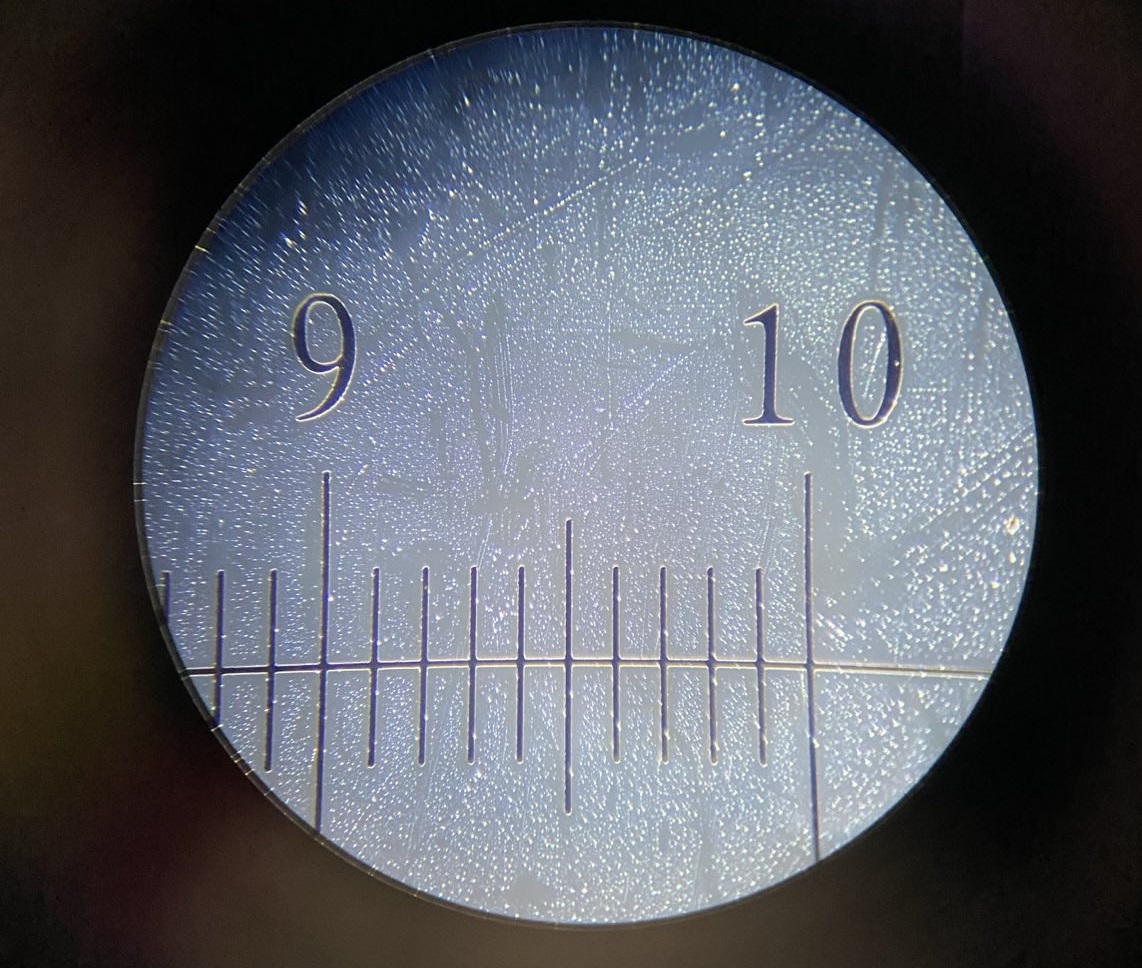
3.1 Basic 100 micrometer calibration
Below are 3 images of a calibration slide with each division/increment separated by 0.1mm / 100 µm at 4 levels of magnification: 1x (no microscope, just taking a picture of the calibration slide), 100x, 400x, and 1000x:

I think we can both agree – pretty crisp!
The above was done using the bright-field setup, since the pure black ink doesn’t scatter much light. For example, using the 100x setup with the dark-field position for the light, yields the following image:
This mostly shows oil/water droplets present from handling the slide without gloves. But for some biological samples, the dark-field setup works very well.
3.2 Biological samples
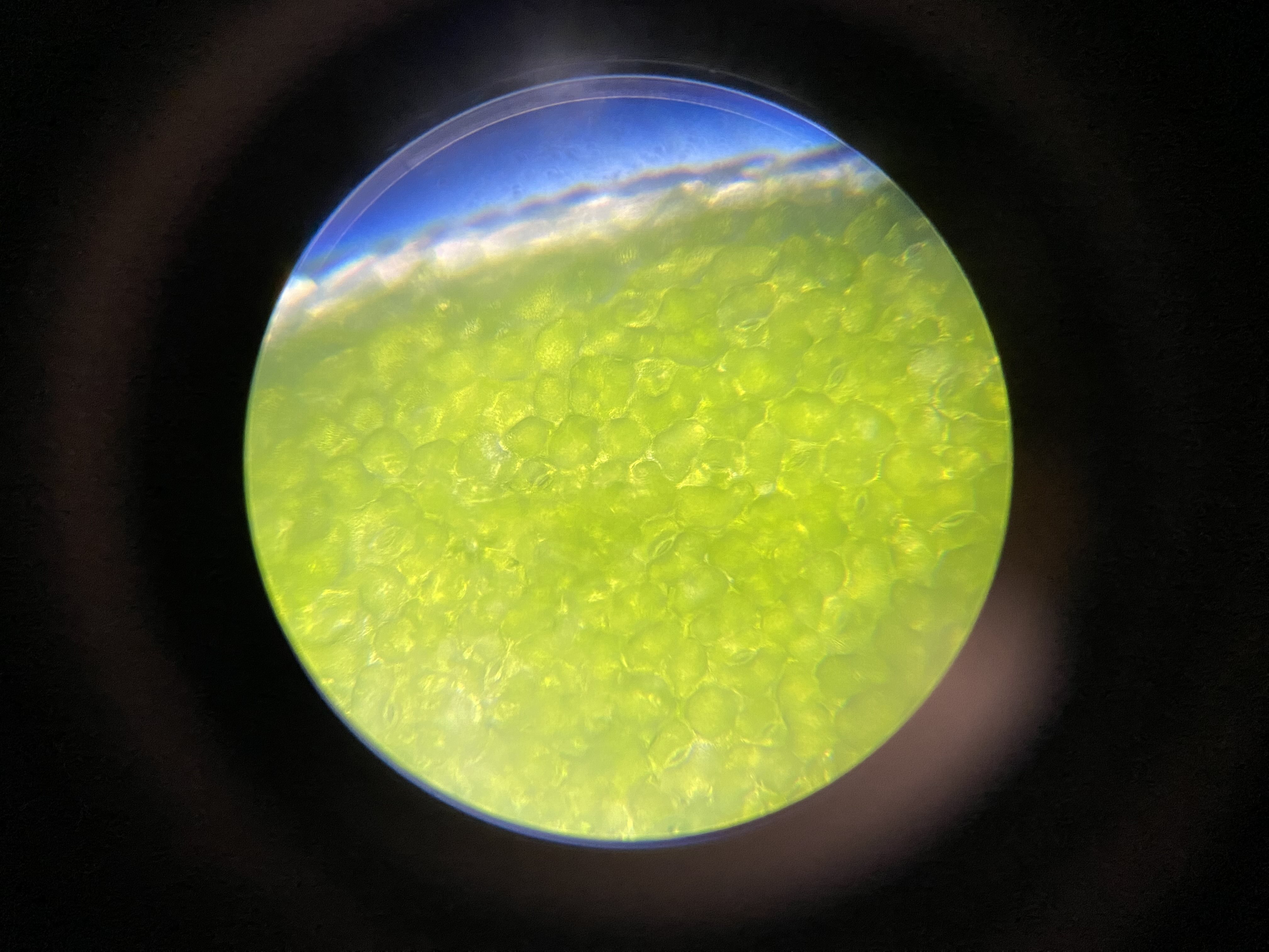
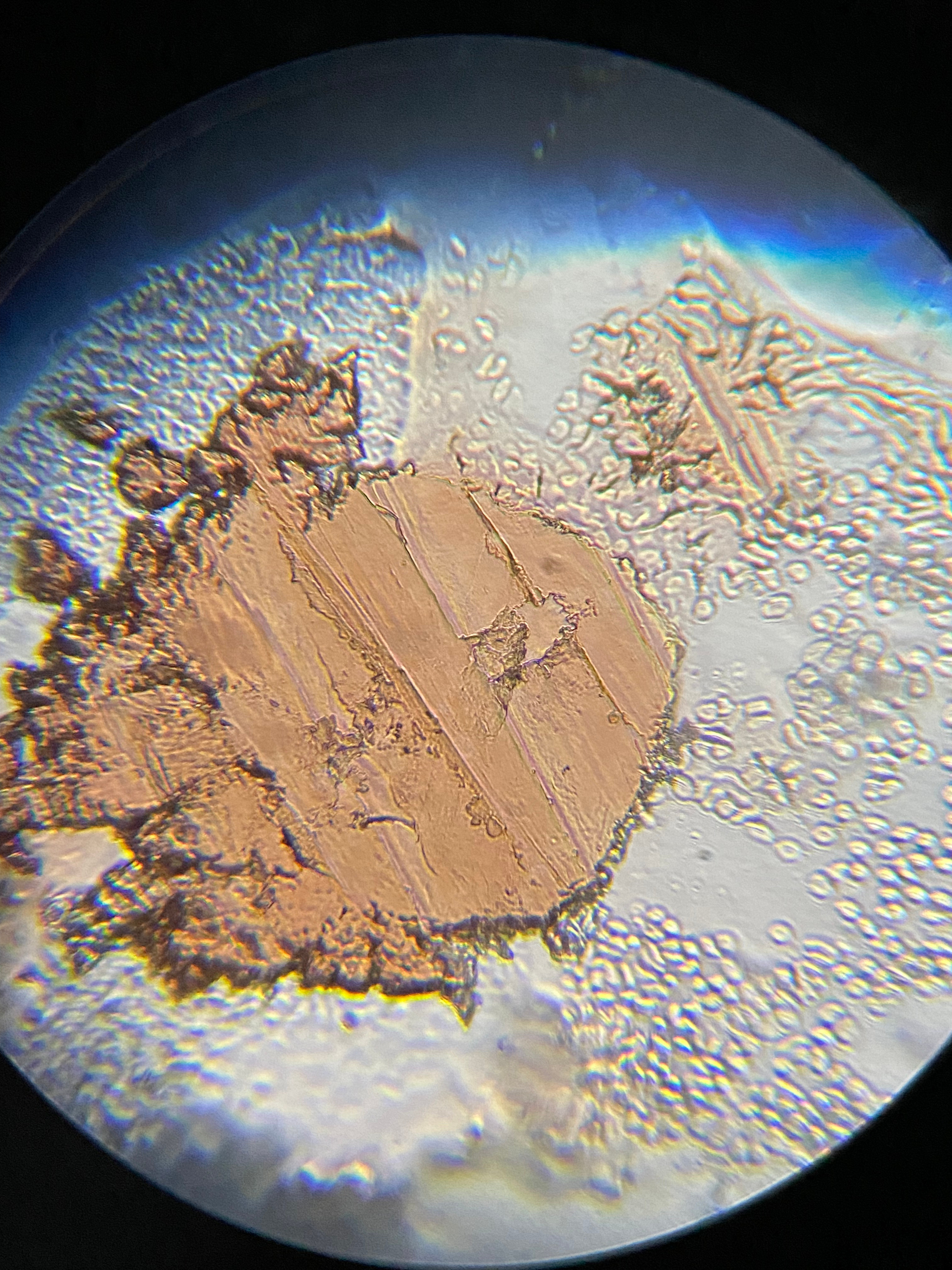
In the following images and videos I show various biological samples, where one can observe the clarity of the microscope, as well as the beauty of the microscopic world. In the samples below, I do not know what all the parts of the image are – i.e. I have not identified all parts of each sample, and I don’t yet have enough faith in AI to trust it’s assessment.
Sample 1: Plant leaf at 400x magnification, showing the leaf boundary.
Sample 2: Plant leaf with some detritus at 100x magnification, showing the leaf boundary. Some out-of-focus critters of some kind are moving in the background.
Sample 3: A solidified scab and surrounding scrapings from a recent cut on a human.
Sample 4: Pond water with several moving critters inside some kind of plant/algae strand, taken at 400x.
Sample 5: Pond water with a single large critter of some kind moving around, taken at 1000x. Several internal components of the organism can be seen when it swims into the optimal focus. If you know what this is – please do let me know.
Sample 6: A section of a dying fly that had just been swatted out of the air, observed at 400x magnification. The tissue appears to be rhythmically twitching.
Beautiful images and clarity indeed, especially considering the price!
Summary
Overall the microscope project was a success, and it has been performing even better than I initially expected such a cheap system would. The only downside is that the body frame – being plastic – isn’t as rigid as precision-worked metal. This can sometimes cause the objective to shift ever so slightly when changing from zooming in to zooming out the focus. However, it is manageable after a little bit of practice if one moves the focusing knob carefully.
I hope you found this post valuable, and I hope it maybe encourages you to get into the microscopy world if it interests you – hopefully cost is becoming less of a barrier these days. Also, if you can identify some of the organisms and parts of the images I’ve taken above, please let me know via the About page – I’d love to learn more about what they are.
As always, thanks for reading!
tags: 3d printing - diy - microscopy